Web Level Monitoring Application Modbus‑TCP Interface
Web Level Monitoring Application Modbus‑TCP Interface is a professional data integration solution designed to connect GaugerNET with SCADA and industrial monitoring systems. This Modbus‑TCP gateway function allows users to securely extract real‑time level, distance, volume, flow, temperature, and position data from field‑deployed GaugerGSM sensors without custom software development. As a reliable industrial communication bridge, Web Level Monitoring Application Modbus‑TCP Interface simplifies system integration, improves data accessibility, and supports seamless remote level monitoring for oil & gas, water treatment, chemical, and environmental industries.
Product Introduction of Web Level Monitoring Application Modbus‑TCP Interface
Web Level Monitoring Application Modbus‑TCP Interface is developed and supplied by Solidat Applied Technologies Ltd., a leading provider of industrial wireless monitoring and communication solutions in China. We deliver stable, certified, and easy‑to‑deploy Modbus‑TCP integration services with full customization support to meet diverse industrial system requirements. Global customers can contact us for product quotations, technical documents, and on‑site support, enjoying high‑quality solutions and competitive pricing.
This interface serves as a standard Modbus TCP gateway, supporting all mainstream SCADA platforms and monitoring software that implement Modbus‑TCP protocols. It offers a practical alternative to direct sensor reading, reducing development costs while maintaining stable data transmission. Web Level Monitoring Application Modbus‑TCP Interface supports both read and write register operations, standard command responses, and exception handling, ensuring full compatibility with industrial automation systems.
Using GaugerNET with Web Level Monitoring Application Modbus‑TCP Interface
The Web Level Monitoring Application Modbus‑TCP Interface converts GaugerNET into a Modbus TCP gateway, allowing external systems to access sensor data efficiently. Direct sensor reading offers higher efficiency but requires software development, while the Modbus‑TCP route provides a plug‑and‑play integration method with minimal engineering effort.
This interface supports Modbus function codes 0x03 (read registers) and 0x10 (write registers). The unit ID in each request is mapped to a specific GaugerGSM sensor name, enabling targeted data reading. Web Level Monitoring Application Modbus‑TCP Interface also returns standard legal responses and proper exception codes for invalid commands, ensuring stable and predictable communication in industrial environments.
GaugerNET Architecture for Web Level Monitoring Application Modbus‑TCP Interface
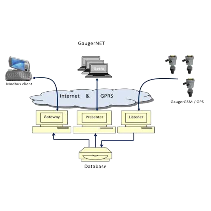
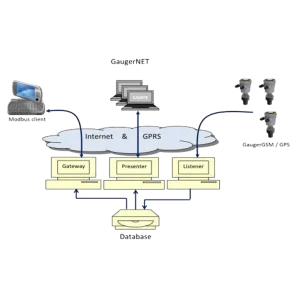
GaugerNET uses a three‑server architecture to support Web Level Monitoring Application Modbus‑TCP Interface: Listener, Presenter, and Gateway. The Listener runs on a Linux server and manages TCP socket connections with GaugerGSM and GaugerGPS sensors, storing all data in a MySQL database. The Presenter provides the web dashboard with charts, tables, and map views. The Gateway runs as a PHP application on Linux and executes the Modbus TCP gateway logic, receiving Modbus requests and replying with data from the database.
This modular architecture ensures high stability, scalability, and security for Web Level Monitoring Application Modbus‑TCP Interface, supporting continuous 24/7 industrial operation.
Modbus‑TCP Message Flow & Process Variables
Web Level Monitoring Application Modbus‑TCP Interface follows strict Modbus message flow rules. A write command (0x10) must be sent first to activate the gateway, which remains active for 10 minutes. After activation, multiple read commands (0x03) can be sent to retrieve process variables such as distance, level, volume, flow, temperature, voltage, RSSI, status, time, and GPS coordinates.
The interface supports a complete set of process variables with defined register offsets, allowing structured and standardized data access. With robust compatibility and clear protocol definitions, Web Level Monitoring Application Modbus‑TCP Interface becomes an essential component for industrial digital transformation and automated remote level monitoring.
Modbus Request Message Function Code 0x10 (Write Registers)
| Byte Range | Description |
|---|---|
| 0-1 | Transaction identifier |
| 2-3 | Protocol identifier 0x00 |
| 4-5 | Length 0x00 / 0x0D |
| 6 | Unit identifier 0x00 |
| 7 | Function code 0x10 |
| 8-9 | Register offset 0x00 / 0x64 |
| 10-11 | Number of registers 0x00 / 0x03 |
| 12 | Bytes to write count (0x06 in the example) |
| 13-18 | Bytes to write (Byte content between 0x21 and 0x7F) |
| Example Frame | 00 01 00 00 00 0D 00 10 00 64 00 03 06 41 42 43 2B 61 62 |
| Example Meaning | Write characters AB C+ ab to registers numbers (decimal) 100, 101, 102. |
Modbus Request Message Function Code 0x03 (Read Registers)
| Byte Range | Description |
|---|---|
| 0-1 | Transaction identifier |
| 2-3 | Protocol identifier 0x00 |
| 4-5 | Length 0x00 / 0x06 |
| 6 | Unit identifier 0x01-0xFE mapped to sensor ID |
| 7 | Function code 0x03 |
| 8-9 | Register offset – process variables |
| 10-11 | Number of registers – process variables |
| Example Frame | 00 01 00 00 00 06 0A 03 00 01 00 03 |
| Example Meaning | Read the following variables from Sensor 10: Distance, Volume, Flow. |
Process Variables Address Mapping
| Process | Offset | Process | Offset |
|---|---|---|---|
| Distance | 0x01 | Month | 0x0C |
| Level | 0x02 | Year | 0x0D |
| Flow | 0x03 | Hour | 0x0E |
| Refill | 0x04 | Minute | 0x0F |
| Volume | 0x05 | LAT deg | 0x10 |
| Temp int | 0x06 | LAT min | 0x11 |
| Temp ext | 0x07 | LAT sec | 0x12 |
| Voltage | 0x08 | LON deg | 0x13 |
| RSSI | 0x09 | LON min | 0x14 |
| Status | 0x0A | LON sec | 0x15 |
| Day | 0x0B |